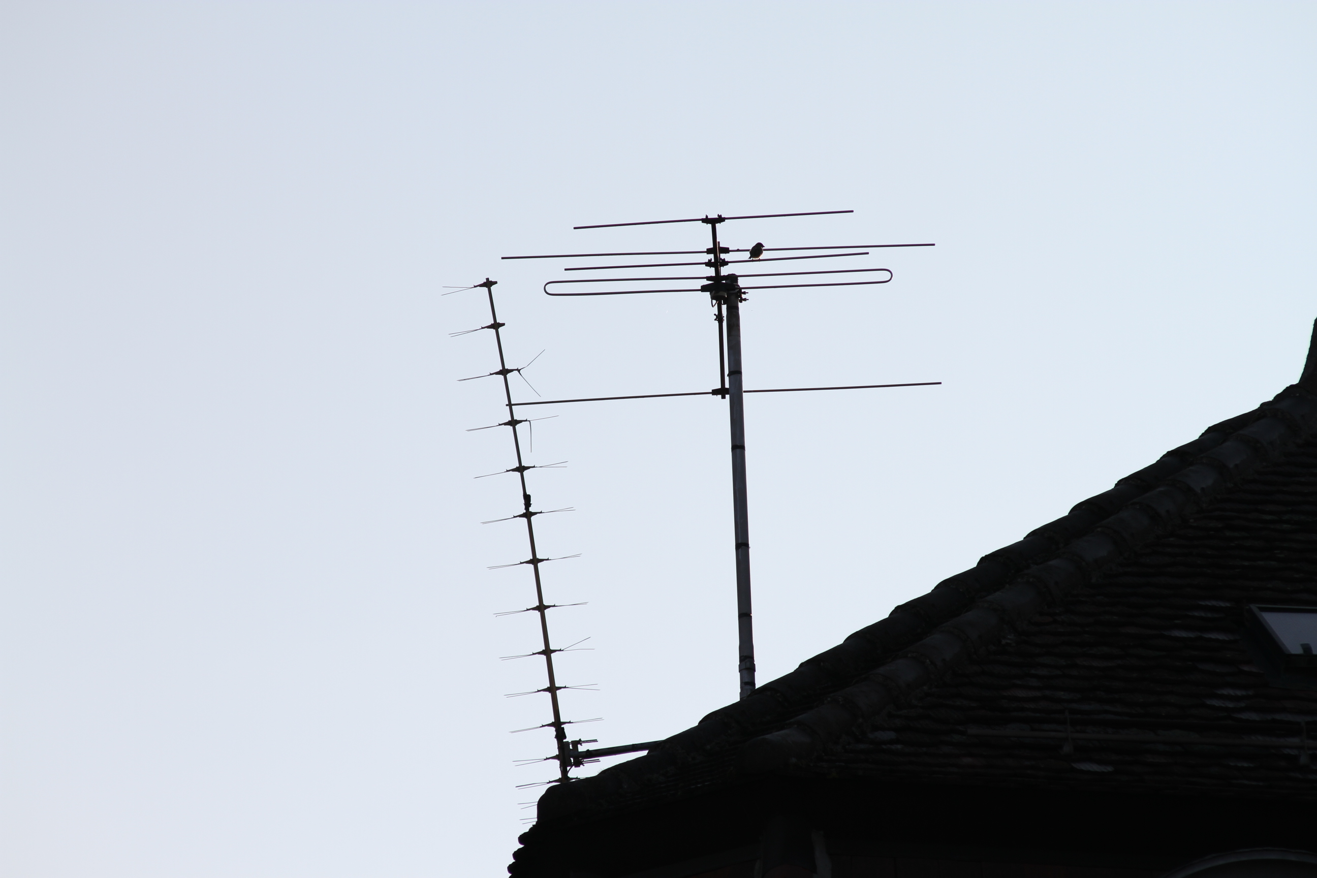
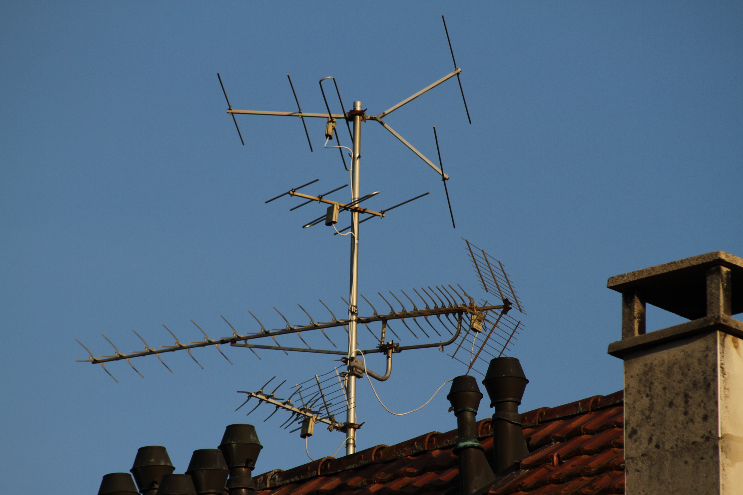
The typical elongated O-shape of the folded dipole is clearly visible in this TV antenna. (click to enlarge)
Folded dipoles are (or were) a very common antenna, present in many Yagi-Uda arrays used for receiving TV and occupying our roofs and the urban landscape for almost half a century. Now, with cable TV and video on demand they are disappearing, and the remaining ones are falling in disrepair but are still present in our environment.
The typical elongated O-shape of the folded dipole is clearly visible in this TV antenna. (click to enlarge)
When I was still a kid and started playing with radio and electronics, many many years ago, I had an antenna book with some basic information on antennas. I remember it had a little paragraph talking about folded dipoles and explaining that their impedance is four times the one of a simple half-wave dipole. I lost that book, but it had an illustration that looked about like this:
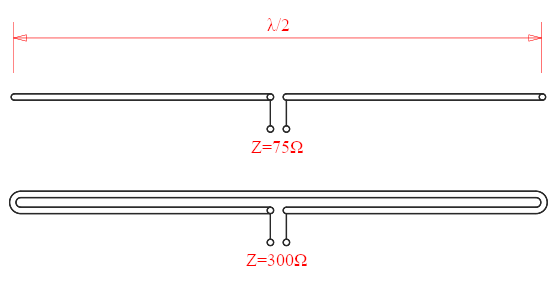
Typical illustration of the impedance of a simple dipole vs a folded one.
I've always been puzzled by this strange fact. There is no doubt that it's true, it stated in many references, e.g. [1, 2, 3], and it's not too hard to measure and verify. But the question is why. Why does the impedance change by folding the dipole? Why adding a second conductor in parallel with a first one actually increases the impedance instead of reducing it? Why doubling the conductors results in a factor of 4 on the impedance? Does it involve a square law, somewhere? Spoiler alert: it turns out it does, there is just the good old P = I2R hidden behind.
Recently I was reading an old book while looking for something else when I stumbled upon a paragraph on folded dipoles [4], and I found the piece of information I was missing to finally understand this phenomenon and I thought I would share.
This is intended to be an intuitive explanation and not a rigorous one. It's not supposed to be 100% accurate but give an explanation good enough to understand what's happening in this antenna and make it easier to remember it. By the way, if you’re looking for a rigorous and mathematically correct explanation, there is a very good one here [5]. The only problem with intuitive explanations is that they only work one way: they explain what they are supposed to do, but cannot be used to deduce other facts, because they are just an approximation, so be careful.
The impedance of a thin half-wave dipole is generally considered to be around 75Ω. It turns out that in this "simple" case it's possible to it calculate analytically, with pencil and paper. The math involved is not easy, but a good and detailed explanation can be found here [6].
A dipole that is exactly half a wavelength long (λ/2), fed at its centre and made with thin wire (diameter smaller than λ/10'000) has an impedance of (73+j42.5)Ω. Note the +j42.5Ω term: the impedance is inductive, indicating that the dipole is slightly too long and not exactly at its resonance. The reason is that the wave is not really in free space, there is the dipole in the way... So, half-wave dipoles are usually cut a few percent shorter to bring them to resonance, 0.47λ to 0.48λ instead of 0.5λ. The thinner the wire, the closer to 0.48λ. At resonance the imaginary part of the impedance drops to zero and the real part is still around 73Ω.
But this is an intuitive description, and we won't bother with these details. Here, we'll consider the impedance a nice, round, purely resistive 75Ω, and we'll simply call it Z.
I split this explanation in 4 steps, just because I find it easier to understand.
Suppose you have a half-wave dipole. Suppose it has no losses and is in free space. A transmitter delivers a given power P at its feed point and a current I = √(P·Z) results. This same current flows in the dipole creating a radiating electromagnetic field around it. Because there aren't any losses, all the power delivered by the transmitter is radiated by the dipole and transferred to the field that carries it away from the antenna at the speed of light.
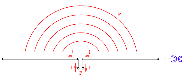
In a normal (non-folded) half-wave dipole, a transmitter delivers a
power P to the antenna, a current I flows and all the power is
radiated.
No imagine splitting the wire in half as indicated by the blue
scissors.
The current I is responsible for the radiation of the antenna. For the moment we don't need to consider the exact current distribution along the dipole, just that the current in the dipole radiates (close to the feed-point the current is high and gradually dies out towards the ends: for this reason the arrow and the symbol I is only drawn close to the centre of the dipole).
The power is radiated in all directions, but for keeping the drawing simple, only a very schematic representation of the emitted wave is drawn; if you want, you can use your imagination to picture yourself a donut-shaped three-dimensional electromagnetic wave radiating away from the antenna at the speed of light... but you don't need to.
Now imagine cutting the dipole in half through its length, as indicated by the blue scissors, so that the thin wire becomes two even thinner wires. This wouldn't be easy to do in practice but just imagine splitting the wires in half, lengthwise. In this way a dipole becomes two dipoles connected in parallel. If the two dipoles are identical they will also split the current in half while the transmitter keeps delivering the same total current I and total power P.
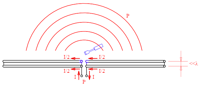
After splitting the wires in half, each carries half of the current
and the dipole works exactly as before.
No imagine rewiring the center of one of the dipoles as suggested by the blue
screwdriver.
Because the two dipoles are very close together (much closer than the wavelength), when looking at them from a distance, no difference is visible, they are too near to tell them apart. Two close and parallel wires each carrying half of the current behave like a single one carrying the whole. So, because the current is the same, the radiation is the same, too. The transmitter still delivers the same current I and the same power P that is radiated in exactly the same way as before.
Now imagine rewiring the centre of one of the dipoles as suggested by the blue screwdriver in such a way that one of the dipoles is still connected to the transmitter as before but the other one runs straight through allowing the current to flow along. Suppose the current in both dipoles is still the same, I/2: from a distance the antenna behaves exactly as before, still radiating the same power in the same way. But now the transmitter only delivers half the current. And because the power is still the same, the impedance must have increased by a factor of 4 as per P = I2Z = (I/2)2/(4Z). And this is where the factor 4 comes from.
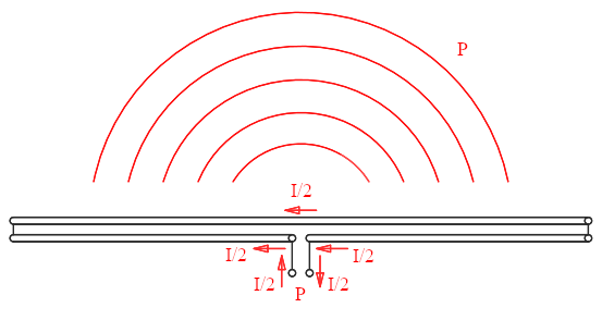
After rewiring, both dipoles still carry the same current, but now the
transmitter still delivers the same power but the current is halved,
therefore the impedance must be 4 times higher.
At first glance, it's surprising that the current in the second dipole stays the same when we disconnect it from the first one and short the two arms together. To get a better picture on this, we have to look at the current distribution that we have ignored so far. In a half-wave dipole the current has a sinusoidal distribution and it's actually a standing wave; it has two troughs at the two tips and a crest in the middle, where the feed-point is. This makes sense, because at the tips the wire ends, the current has nowhere to go and must be zero.
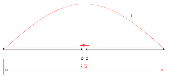
Current distribution in a half-wave dipole.
If now you extend this half-wavelength λ/2 dipole on one side up to a full wavelength λ, the current distribution is still sinusoidal, still has two troughs where they were before, but also an additional one at the farther tip. And now there are two crests. On one half of the antenna the current is, say, positive and flows in one direction, on the other half the current reverses and flows the other way around.
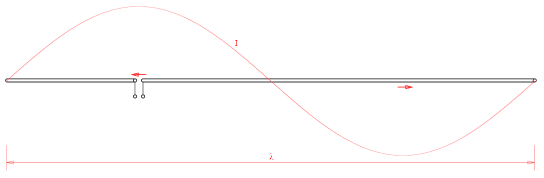
Current distribution in a full-wave dipole; the current on the left
half and on the right half flow in opposite directions.
Now, imagine folding the antenna at half-wavelength, as indicated below by the blue arrow until you obtain a folded dipole.
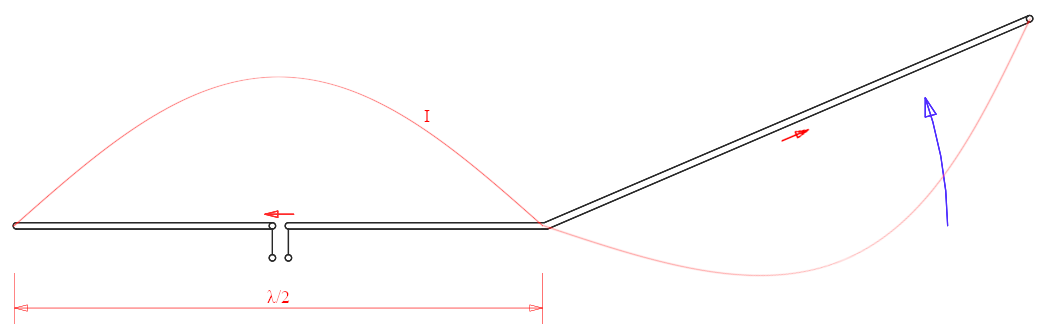
Now imagine folding the full-wave dipole in half as indicated by the
blue arrow.
Folding the antenna in half has the effect of reversing the current on the half of the antenna where the current was already reversed making it flow in the same direction as the other one. The magnitude of the current in both halves of the antenna is the same, after all it's the same current I flowing in the same wire. Also, after one wavelength (360°) the voltage is the same, so the two tips that are now on the left can be connected without creating any short circuit, as represented by the blue screwdriver. What we have now is a folded dipole.
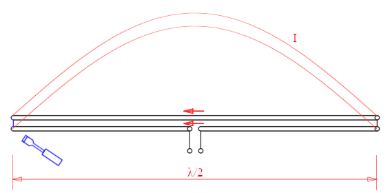
After folding the full-wavelength dipole in half, both currents are
now flowing in the same direction.
And because the total length is one wavelength, the voltages at both ends on
the left side are equal and in phase and can be connected without causing any
short circuit, as suggested by the blue screwdriver.
We now have a folded dipole.
Another way of looking at the folded dipole is as two half-wavelength dipoles connected in parallel at their tips. Here, the current is zero, but the voltage is high. So, the first dipole if fed at its centre with a current coming from the transmitter. The voltage at its ends feeds the second dipole from its ends and the resulting current is in phase with the first one.
This same trick can also be used to obtain different impedances. For example, by splitting the simple dipole in three instead of two, we achieve an impedance 32 = 9 times higher, i.e. 75Ω·9 = 675Ω, because the transmitter now delivers the same power with one third of the current.
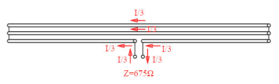
A triple folded dipole with a 9 times higher impedance.
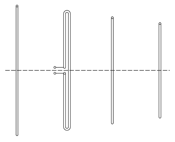
By using more wires and/or different combinations of wires in parallel it's possible to achieve different impedances, like this one where the transmitter delivers 2/3 of the current and has a ratio of (3/2)2 = 2.25 for an impedance of 75Ω·(3/2)2 = 169Ω.
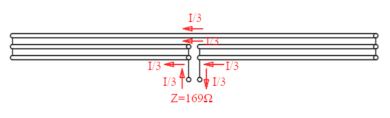
A triple folded dipole with a 2.25 times higher impedance.
The reason why each dipole carries the same current is because they all have the same dimensions, but different currents can also be achieved with different wire diameters. The thicker wire carries the larger current, symbolized below by a longer arrow. Charts are available to estimate the impedance from the diameter ratio, for example in [2].
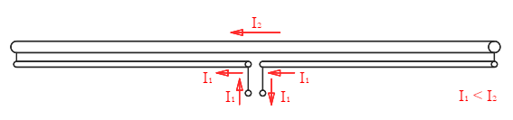
In an unsymmetrical folded dipole the larger conductor carries the larger current and by selecting suitable diameters any impedance larger than 75Ω can be achieved.
A quarter-wave monopole over a ground-plane has an impedance of one half of the free air half-wave dipole. This is often illustrated as follows:
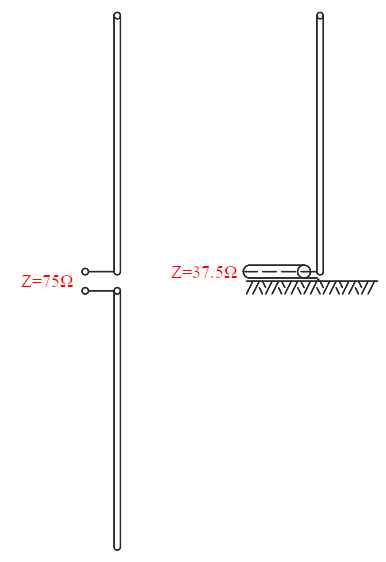
The impedance of a half-wave dipole is 75Ω and of a quarter-wave monopole is 37.5Ω.
But this has nothing to do with the trick of the folded dipole explained in this page. Here, the explanation is purely in the symmetry of the antenna. Let's have a look at the following illustration where a half-wave dipole is transformed into a quarte-wave ground-plane monopole. The drawings at the top show the antenna configuration, while the ones at the bottom show the antenna impedance which is its equivalent circuit.
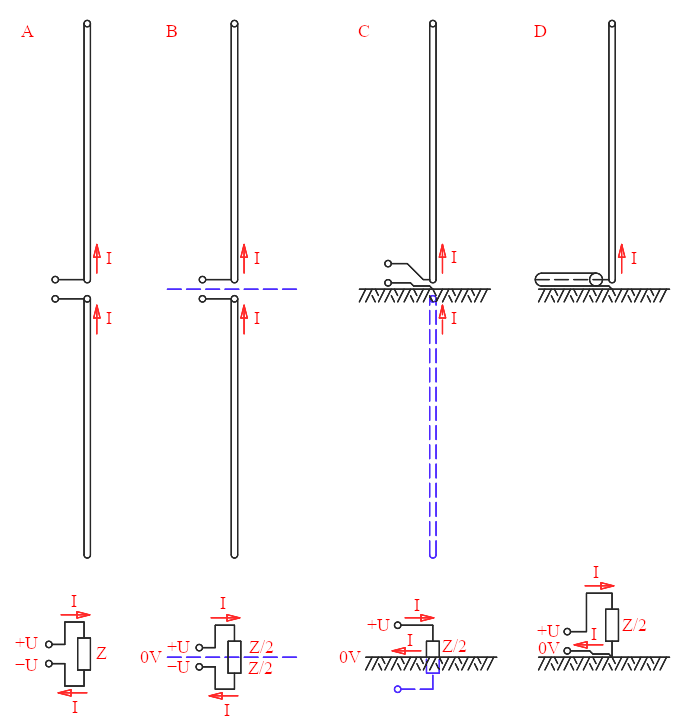
How a dipole transforms into a monopole and what happens to its
impedance.
Let's start with A where we see a half-wave dipole. The transmitter applies a positive voltage +U on the upper terminal and a negative voltage −U at the lower terminal and a current I enters the antenna on the upper terminal and returns from the lower one. The impedance Z of the antenna sets the current to I = 2U/Z (Ohm's law). The total voltage is 2U because it goes from +U to −U.
The dipole is symmetrical: there is a midplane that cuts it into two halves, represented in B as the blue dashed line. Because one half has the positive voltage +U and the other one has the same but negative voltage −U, the symmetry plane must also cut this potential in half, i.e. it must be at zero Volts. The impedance is also cut in two halves of Z/2 connected in series.
An ideal ground plane is an infinite flat and perfect conductor. It behaves like a mirror for the electromagnetic waves. Real ground is not perfect but still works, especially if the terrain is not too rough and relatively wet. For broadcast antennas, it's common to bury copper wires all around the antenna to increase the conductivity.
If the ground plane is coincident with the plane of symmetry of the dipole, it will reflect the upper half of the antenna transforming a monopole into a dipole as shown in C. So, a quarter-wave monopole becomes a half-wave dipole once reflected in the plane. But now the transmitter only delivers half the voltage (from +U to 0V instead of from +U to −U) and sees half of the impedance as the current I returns from the ground. So, the impedance is only Z/2 or 37.5Ω as represented in D.
It must be said that now the transmitter only delivers half the power, but the antenna only radiates in half the space as there is no physical wave below ground, so everything still checks out.
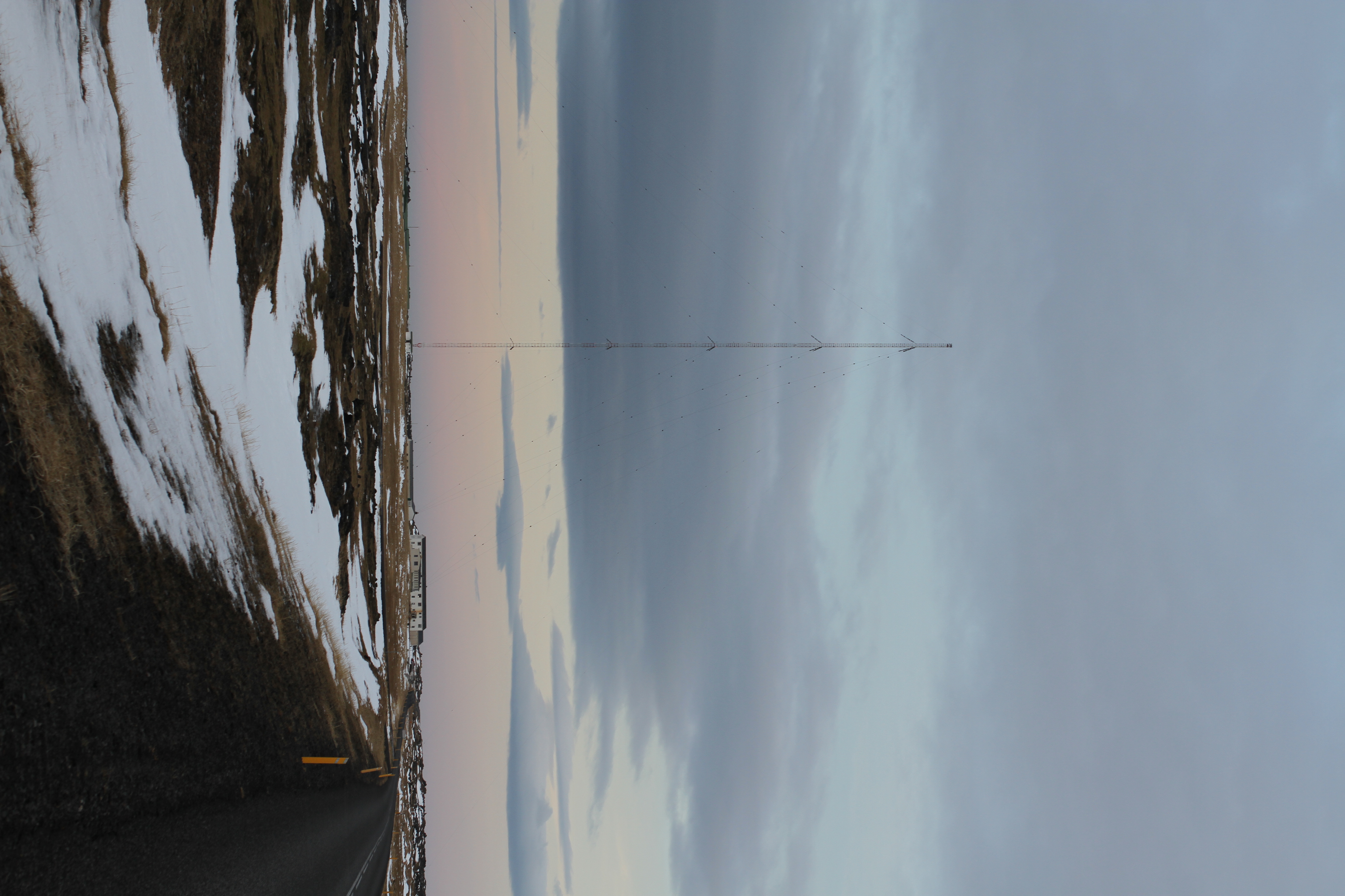
The Hellissandur (RUV) longwave transmitter in Iceland has a mast 412m
tall, is almost exactly a quarter wavelength at its operating frequency
189kHz where it transmits 300kW.
It’s the perfect example of ground-plane antenna.
This picture was taken in January 2016. (click to enlarge)
Please note that here we're talking about ground-plane antennas that use the real ground (the one you can walk on it) as ground plane. This ground plane is not resonant. This is often called "buried radials ground plane antenna" as copper wires are often buried close to the antenna to increase ground conductivity.
We are not talking about "elevated radials ground-plane antennas" that have (usually) four horizontal quarter-wave radials and one vertical quarter-wave monopole and are usually mounted on roofs or poles. It turns out that when the radials are horizontal, this explanation still holds and the impedance is still around 37.5Ω. But in this antenna, if the radials are tiled down the impedance increases and I don't have an intuitive explanation for this phenomenon, unfortunately.
Further information on ground-plane antennas can be found in [9, 10, 11, 12].

This elevated-radials ground-plane antenna has 3 radials tilted down
at 45°: this has the effect of increasing the impedance around 50Ω,
but I don't have an intuitive explanation for this. (click to enlarge)
There are two applications of this trick that come to my mind: Yagi-Uda arrays and multi-tuned flat-top long-waves antennas. Let's have a closer look at them.
In Yagi-Uda arrays, passive dipoles (called "parasitic elements") are added in front and behind the driven element to increase its gain. These elements have the side effect of lowering the impedance of the driven dipole, especially if the spacing is small [7]. For an easier match to a common 50Ω or 75Ω cable a folded dipole is often (but not always) used.
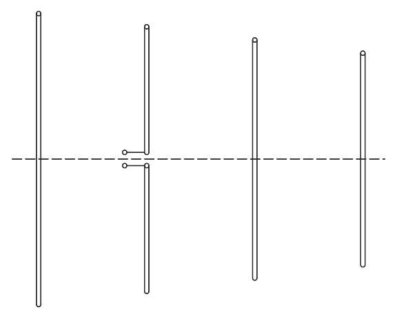
If the impedance of the driven element of a Yagi-Uda antenna is too
low (left drawing), it's often replaced with a folded dipole (right drawing)
to increase its impedance and facilitate the matching to the 75Ω or
50Ω of a common cable.
Hereafter a few pictures of TV antenna masts I spotted on various houses. Can you find all the folded dipoles? The answers are in the description of each picture.
The two Yagi-Uda antennas on the top of this rooftop TV antenna
installation use a folded dipole as driven element, the two on the bottom
don't. (click to enlarge)

The folded halo-antenna on the top of this mast is used for FM
reception and is a folded dipole, the two antennas in the middle look like
having folded dipoles but are not (these are just doubled/thicker normal
dipoles), and the antenna on the bottom has a nice folded dipole.
(click to enlarge)
Another application is to increase the impedance in long- and very-long-waves antennas. At frequencies around 100kHz and below, the wavelength becomes very long, several kilometres. In these bands, antennas are often a vertical ground-plane monopole or some variation of it, but it can be impractical or too expensive to build towers a quarter wavelength tall.
As the length of the antenna is shortened from its resonance, the reactive part of the impedance increases rapidly becoming capacitive, the resistive part drops, and the loss resistance becomes dominant over the radiation resistance. It's not uncommon to have a reactance measured in kiloohms, losses measured in Ohms and a radiation resistance in tenths of milliohms [8].
Shortening the antenna reduces the efficiency in several ways. First, the current in the antenna is reduced and, unfortunately, the current is responsible for radiation. This is illustrated in the following image where e normal quarter-wavelength monopole (in A) is shortened (in B): the current has the usual sinusoidal distribution with always a node at the tip (where the wire ends) and must be zero. But now there isn't enough space to reach the maximum at λ/4, therefore the current is lower and the part of the antenna where the current is high is also shorter. This explanation is not 100% correct, as the current is the one delivered by the transmitter and can have any value, it would be more accurate to say that the impedance is lowered, but it's just to give an idea of what happens.
A capacitive hat (in C) helps in not reducing the current as much, because now the end of the wire is farther away. A horizontal conductor over a vertical radiator is commonly called a hat: in its simplest form it makes a "T" but can also have a more complex shape like an umbrella. The hat doesn't radiate much because the two currents are low and flow in opposite directions cancelling their effect. But because the hat is not small compared to the wavelength there is still some contribution to the radiation.
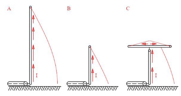
Current distribution in a λ/4 monopole (A), a short monopole
(B) and a short monopole with a capacitive hat (C).
Second, the radiation resistance is reduced and the resistive losses become comparatively larger. To minimize losses the size and number of the conductors is usually increased, and ground conductivity is improved by burying numerous radials in the ground. Common buried ground planes have a conductor every 3°, usually as long as the antenna is tall, but every antenna is different.
Third, the large capacitive reactance of the antenna requires large inductors to bring the antenna back to resonance. Inductors are lossy and expensive, especially if built with a large conductor. A capacitive hat is beneficial also in this regard as it reduces the reactance and a smaller inductor is required. Furthermore, the low resistive part of the impedance must be matched to a common impedance like 50Ω for the transmitter to work, and the lower the impedance the higher the losses in the matching network.
To improve this situation, here too, we can use the same trick of the folded dipole: we replace a single monopole with multiple ones splitting the current and obtaining a multiple-tuned flat-top antenna which has a much higher impedance and lower losses.
This antenna has a large horizontal flat capacitive hat. As explained before, the hat doesn't radiate much but helps making the antenna electrically longer and increases the current in the vertical elements. The vertical elements are the actual monopoles that radiate, the actual radiators. Because these monopoles are short, they are tuned with an inductor each to make them resonant at the desired frequency.
If you ignore the capacitive hat and the inductors, it's like a folded dipole with multiple branches we have described before but rotated by 90° to make it vertical and with the lower half missing, as it's reflected in the ground-plane. Yes, some imagination is required here...
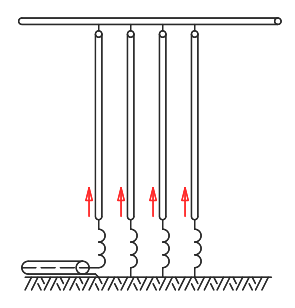
A multiple-tuned long-waves antenna.
Because the current is split equally between the multiple monopoles, the losses are reduced, too, because they obey P = I2R. In fact, the sum of the losses of many small currents is smaller than the losses of a single equivalent one. The impedance is also higher.
A perfect example of this antenna is the one used by SAQ in Grimeton, Sweeden, that transmits on 17.2kHz. Unfortunately, I don't have a picture of it.
An antenna may look like just some pieces of metal thrown together, but there is a logic behind. When I see an antenna, I like to take the time to look at it, try to understand how it works, try imagining what the designer was thinking when he conceived it and what compromises he chose and why. Here, I talk only about two specific antenna types, but there are many more with many other clever tricks that would also deserve to be described; antennas are such a broad topic that cannot be covered in a single and simple page.
This is my take at explaining folded dipoles and short monopoles in an intuitive way. I hope my intuitive way is intuitive enough to be useful to somebody else. Again, don't take it as a formal exact explanation, but as one of the many ways to describe what's going on. Unfortunately, to understand antennas, some background in electromagnetism is necessary and I take it for granted, so this document is intended for skilled amateurs, if this term makes sense.
| [1] | N. Neri, I4NE. Radiotecnica per radioamatori. C&C, 1990, page 226. |
| [2] | N. Neri, I4NE. Antenne - Linee e propagazione. C&C, 1982, pages 132-133. |
| [3] | R. D. Straw, N6BV. The ARRL Antenna Book, 19th edition. American Radio Relay League, 2000, page 26-8. |
| [4] | E. A. Laport. Radio Antenna Engineering. McGraw-Hill, 1952, pages 252-253. |
| [5] | C.-A. Balanis. Antenna Theory, Analysis and Design. Wiley, 1997, Section 9.5, pages 458-462. |
| [6] | C.-A. Balanis. Antenna Theory, Analysis and Design. Wiley, 1997, Section 4.6, pages 162-164. |
| [7] | C.-A. Balanis. Antenna Theory, Analysis and Design. Wiley, 1997, Section 10.3.3, pages 513-533, especially table 10.5. |
| [8] | E. A. Laport. Radio Antenna Engineering. McGraw-Hill, 1952, Section 1.10, pages 38-39. |
| [9] | C.-A. Balanis. Antenna Theory, Analysis and Design. Wiley, 1997, Section 4.8.1, pages 182-185. |
| [10] | N. Neri, I4NE. Antenne - Progettazione e costruzione. C&C, 1986, pages 46-55. |
| [11] | N. Neri, I4NE. Antenne - Progettazione e costruzione. C&C, 1986, pages 136-139. |
| [12] | C.-A. Balanis. Antenna Theory, Analysis and Design. Wiley, 1997, Section 9.4.3 & 9.4.4, pages 451-454. |
| Home | Electronics | Page hits: 013399 | Created: 04.2025 | Last update: 04.2025 |