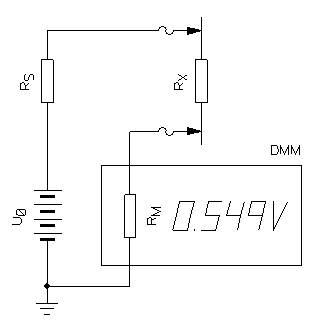
Circuit diagram of the measurement setup.
A digital multi-meter (or DMM) is a very handy tool in the lab and is your trusty friend for the majority of simple electrical measurements. It can measure voltage, current, resistance and often a lot more. It can accurately handle the values you want to measure almost all the time: just connect the leads, select the desired function, the appropriate range (if needed) and you're ready to go.
But there are times you wish it could do a little more. For example, I once wanted to measure the insulation resistance of some materials. Here, we're talking about GΩ (giga-Ohms, 109Ω) and maybe TΩ (tera-Ohms, 1012Ω). You cannot measure that with a DMM... or can you?
Well, the correct instrument for that is an electrometer. It's accurate, it can measure up to several PΩ (peta-Ohms, 1015Ω) but it costs as much as a new car... and most sadly, I don't have one. The best multimeter I have can read resistances up to 50 MΩ (mega-Ohms, 106Ω), average (cheap) DMMs read up to 10 or 20 MΩ... what I would like is to read values about 1'000 times or even 10'000 higher. Hopefully, there is a very simple trick that allows extending the range; it's by far not as accurate as an electrometer, but it's much better than nothing. And all you need is your DMM and some batteries. Let's have a look.
When you select the resistance function of your DMM, it will supply a small DC voltage on its leads so that a current can flow through the unknown resistor, it will adjust this current to some convenient value and by reading the voltage, the current and using Ohm's law it will display the corresponding resistance. If the resistor is too large, the little voltage won't be able to flow enough current and the DMM will display an over-range message. So, the first part of the trick is to help the DMM by suppling an external voltage, higher than what it can normally provide and measure the current in the unknown resistor.
Usually, when you want to measure current, you simply select the current function of your DMM: the display reads directly in Amperes and the input impedance is very small so that you don't disturb your circuit too much. But you can only read down to 1 mA, maybe 100 μA or even a little less, depending on your DMM, but the current flowing in a high value resistor is much much lower, say 1 nA (nano-Ampere, 10−9A) or less. The "current" function of your multimeter won't help you here.
But the solution is very simple: just use the voltage function instead: you're simply measuring the voltage across its large input impedance, say 10 MΩ or so. If you read 10 mV, over 10 MΩ, that's 1 nA. If you read 1 mV, that's 100 pA (pico-Ampere, 10−12A). In a normal situation a 10 MΩ shunt resistor would be unreasonably high to allow any practical current through it, but here the resistances we are trying to measure are so large that 10 MΩ is a very convenient value.
So, the setup will look something like this: you need an external test voltage source U0, an optional safety resistor RS, your trusty multimeter (with its input impedance RM) and of course a high value resistor to measure RX. Well, maybe you also need a pocket calculator or the calculator embedded in this webpage.

Circuit diagram of the measurement setup.
The circuit diagram is represented in the above figure and is also very simple: everything is just connected in series. You don't really need to connect the negative terminal of the battery to ground (even if it's not a bad idea): the ground symbol is just to remind where the 0 V reference for the measurements is.
The equation to calculate RX is simply the "voltage divider" divider formula modified to include RS:

Let's take an example: suppose your test voltage U0 is 50 V, your multimeter has an RM of 10 MΩ and your safety resistor RS is 1 MΩ. If your DMM measures 500 mV your resistor under test RX is 989 MΩ; it's as simple as that.
When doing these measurements, make sure you let enough time to the stray capacitances to charge and reach a steady state. Remember that 10 pF and 100 GΩ have a time constant of one second... if you see that the values are still moving wait a few seconds until the reading is stable.
Before having a look at all these elements one by one to discuss how to choose them and their pros and cons, here is a simple calculator that will figure out the resistance in just one click.
We have seen before that formula to determine resistance is quite simple, but it can be tedious to do the math by hand on a pocket calculator, so I created this simple tool to automate the operations. Simply enter the values for U0, RM, RS and UM and hit the "calculate" button to find RX. If you know the uncertainty on the voltage you measured, enter ΔUM as well and you'll also get the minimum and maximum limits of the calculated resistance. If you don't care, just use 0 or ignore those values.
Use the best and most accurate multimeter you have. You'll be pushing the limits very far, every little error will degrade your results: use the best you have on hand. You also need to know its input impedance as accurately as you can for (all) its DC voltage ranges. It's usually around 10 MΩ and maybe it's written on its datasheet, but also depends on the voltage range you're using and most probably on the very instrument you have in your hands. So, my suggestion is to measure it. Try with another DMM if you have an extra one on hand.
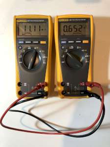
Using another multimeter to measure the instrument impedance. (click to enlarge).
My Fluke 179, for example, has a very vague datasheet stating only "input impedance: >10 MΩ"... not good enough for any calculation. So I measured it with another Fluke 177 and I could determine the following impedances:
| Range | Input impedance RM |
| 600 mV | 10.00 MΩ |
| 6 V | 11.12 MΩ |
| 60 V | 10.11 MΩ |
| 600 V | 10.02 MΩ |
| 1000 V | 10.01 MΩ |
The input impedance depends on the range you're using. Make sure you know which range is selected and use the correct value, especially if your DMM is auto-ranging.
When doing this measurement, make sure the voltage provided by the DMM measuring the resistance doesn't exceed the range of the DMM being measured. For example, if you're trying to measure the input impedance of the 600 mV range with a 2.5 V test voltage, you'll probably end up with a wrong value, because the overvoltage protection of the DMM may change the impedance.
If you only have one DMM or if your DMM is not up to the task, you can still determine the input impedance by measuring a known high value resistor with the method described in this page and adjust the impedance to match the calculated value to the real value of the resistor. I use a 10 MΩ resistor, because it can also be measured directly with the DMM and it's a value that is still easy to find (larger values are uncommon). You can also use several 10 MΩ resistors that can all be measured individually and then connected in series to form a larger resistor of known value.
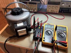
Measuring a 10 MΩ resistor to verify the instrument input impedance. (click to enlarge).
We need an external voltage source to perform our measurements. The higher the voltage the better the precision. But let's be reasonable: be safe, stay below 50 V. For example, use five 6LR61 9 V batteries in series: you'll get 45 V, probably even a little more with brand new batteries and everything is safe to touch. Since there is almost no current flowing in the resistor under test (it's almost an insulator), voltage sag due to the connection of the load is by far not an issue.
Up to 50 V everything is safe to touch, nothing bad will happen. Using a higher voltage will make the measurement more accurate or allows measuring higher resistor values, but it's a risky business. I do it, but I strongly recommend not to. If you do, you should really know what you're doing. Do it at your own risk.
You must use a DC voltage for this. The reason you cannot use AC is because any stray capacitance would play a major role and spoil your measurements: at 50 Hz even a tiny pF across your resistor under test would introduce a parallel reactance of 3 GΩ : looks large at first glance, but it's too small to be neglected.
The safety resistor RS is not strictly needed, but it's a good idea. I usually use 1 MΩ, but this value is not critical. Its role is to limit the current should you accidentally make a short circuit or touch something you shouldn't.
A short circuit to ground of a 500 V source through a 1 MΩ resistor will result in a current of only 500 μA: I didn't test it (that would be silly), but it shouldn't bite your finger if you accidentally touch it and should probably also prevent from zapping your nice DMM if your resistor under test looks more like a short circuit than an insulator. It's a cheap insurance: it won't work miracles but it may help.
1 MΩ is small enough to be neglected, but is also very easy to subtract it from the final result. In the calculator in this page I included it as well. If you're not using it, or if you're measuring U0 after the safety resistor, simply type "0" as value for RS.
Due to the very high impedances involved in this setup, measurements can be affected by errors due to interference. We already said that using DC is very important to prevent effects from stray capacitances, but nearby electric and magnetic fields can also introduce errors. Not all multimeters are shielded as they should be, not all of them are insensitive to AC components coupled oved a tiny DC voltage as they are supposed to be. Before doing any measurement, prepare your setup and make sure that you read zero volts when the supply voltage is not energized (or not connected). If you don't, move everything inside a metal box to shield your setup from interferences.
You'll also remark that simply moving your hands or body around changes the readings a little bit. If everything settles to zero when you stop moving you're fine, if you're influencing the measurements too much, move all your setup in a metal container.
Before we look into the accuracy issue, we should keep in mind that the resistance we are measuring varies as 1/UM: the smaller the voltage the larger the resistor. But this also means that a tiny error on a tiny voltage yields to a large uncertainty on the resistance. Additionally, UM is directly proportional to U0: a higher test voltage yields to a higher measured voltage: if the uncertainty on the measured voltage is the same, this increases the accuracy of the result. The following table shows the voltages one expects to measure for five different resistors and four different test voltages.
| Expected voltage UM | Test voltage | ||||
| U0 = 15 V | U0 = 50 V | U0 = 150 V | U0 = 500 V | ||
| Resistor to measure RM |
100 MΩ | 1'363.6 mV | 4'545.4 mV | 13'636.4 mV | 45'454.6 mV |
| 1 GΩ | 148.5 mV | 495.1 mV | 1'485.2 mV | 4'950.5 mV | |
| 10 GΩ | 15.0 mV | 50.0 mV | 149.9 mV | 499.5 mV | |
| 100 GΩ | 1.5 mV | 5.0 mV | 15.0 mV | 50.0 mV | |
| 1 TΩ | 0.2 mV | 0.5 mV | 1.5 mV | 5.0 mV | |
Not all the digits on the display of your DMM are accurate and to know how accurate a measurement is one should refer to the instrument datasheet or, even better, to its calibration certificate. Let's imagine that we measure these voltages with an accuracy of ±2 mV: the following table shows the error on the calculated resistance value.
| Measured RM accuracy with an error of ±2 mV on UM |
Test voltage | ||||
| U0 = 15 V | U0 = 50 V | U0 = 150 V | U0 = 500 V | ||
| Resistor to measure RM |
100 MΩ | +0.16 MΩ −0.16 MΩ |
+0.048 MΩ −0.048 MΩ |
+0.016 MΩ −0.016 MΩ |
+0.0048 MΩ −0.0048 MΩ |
| 1 GΩ | +0.014 GΩ −0.013 GΩ |
+0.0041 GΩ −0.0041 GΩ |
+0.0014 GΩ −0.0014 GΩ |
+0.00041 GΩ −0.00041 GΩ |
|
| 10 GΩ | +1.5 GΩ −1.2 GΩ |
+0.42 GΩ −0.39 GΩ |
+0.14 GΩ −0.13 GΩ |
+0.040 GΩ −0.040 GΩ |
|
| 100 GΩ | +∞ GΩ −57 GΩ |
+67 GΩ −29 GΩ |
+15 GΩ −12 GΩ |
+4.2 GΩ −3.8 GΩ |
|
| 1 TΩ | +∞ TΩ −0.93 TΩ |
+∞ TΩ −0.80 TΩ |
+∞ TΩ −0.57 TΩ |
+0.6667 TΩ −0.2857 TΩ |
|
Let's take an example: if you measure a 10 GΩ resistor with a 50 V test voltage, we have seen before that your multimeter should show 50 mV. If you have a ±2 mV error on this value, you expect the real voltage to be within 52 mV and 48 mV, corresponding to 9.61 GΩ and 10.42 GΩ. The table tells you that this value is within −0.39 GΩ and +0.42 GΩ from 10 GΩ, which is the same thing.
As one can see, the uncertainty on the resistance quickly gets very large for large resistances: it's easy to measure 10 GΩ quite accurately with just 50 V; to measure 100 GΩ a higher voltage would be better if you think you can handle the risk. And to measure 1 TΩ... well, not only you need a high voltage, but also a very accurate DMM: if you can read 5 mV ±0.2 mV (this is what my Fluke 179 can do), with a test voltage of 500 V you can read 1 TΩ within −0.038 TΩ and +0.042 TΩ. With a better DMM you could certainly do better. But beware of high voltage: I warned you, do it at your own risk.
In any case, even if this method becomes less accurate for large resistances and you cannot determine a precise value when measuring only a few millivolts, still this measurement may be useful and much better than nothing. For example, when comparing two insulators, that tiny little voltage may be enough to show some leakage and help you pick a better material, even if it won't allow you to precisely determine its resistance.
The error on a multimeter is often expressed with two terms: a percentage on the reading and an absolute error on the counts. For example, my Fluke 179 is specified ±0.09% and ±2 counts in the 600 mV range, a "count" being one unit of the rightmost digit. This means that if I read, say 315.7 mV, the first term will introduce ±0.3 mV of error and the second ±0.2 mV for a total of ±0.5 mV: the actual voltage is somewhere between 315.2 and 316.2 mV. On the other hand, if I read 12.5 mV the first term contributes now for only ±0.011 mV, but the second one is still ±0.2 mV and the actual voltage is somewhere between 12.3 and 12.7 mV.
I know it's dangerous, but when I need the extra precision, I do use a high voltage source. But I know what I'm doing (I hope) and I take all the necessary precautions. For example, always disconnecting everything twice (switch off and unplug) before touching any part is a good habit. Also, short circuit the high voltage lead to ground with an insulated probe before touching it is another good habit. And keeping an extra voltmeter always connected to make sure the voltage really went to zero is also good idea. But this is up to you: I recommend that you don't do it, but if you play with dangerous voltages (more than 50 V) you should already know all this stuff and a lot more. So do it at your own risk.
This being said, I often need a high voltage (couple of hundred volts or so) for many applications, this being just one. Others are for powering vacuum tubes or gas discharge tubes. I normally use a variac to adjust the mains voltage anywhere between 0 and 280 VAC, simply because this is what my variac is capable of. I then rectify and filer this voltage to get an adjustable DC voltage between 0 and 400 VDC. To simplify the setup, I built a little box with a rectifier, a filter capacitor, a load cutoff switch, a bleeder resistor and a pilot light. Since I find that it's a handy device when you need high DC voltage, here is the schematic diagram:
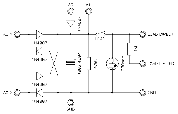
Circuit diagram of my rectifier-filter box.
It allows using a full wave bridge rectifier or a half wave (simple diode) rectifier, depending if there needs to be a ground connection or not. Keep in mind that the neutral wire of your mains supply is most probably grounded somewhere in your electrical distribution box. My variac is a true transformer with an insulated secondary winding, but most variacs are simple autotransformers with no insulation from the mains supply line; in this case, an additional isolation transformer is a good idea. Again, make sure you know what you're doing here.
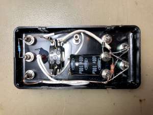
Picture of the inside of the rectifier filter box. (click to enlarge).
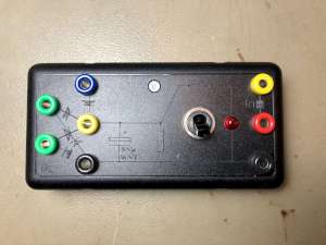
Picture of the front panel of the rectifier-filter box. (click to enlarge).
Let's now have a look at some examples, let's measure some large resistances. After setting up the voltage source and the instruments, the first thing to do is to test it with no resistor at all: after a few seconds of stabilization the DMM settles to 0.0 mV: good news, there are no interference problems. Then, let's try a 10 MΩ resistor: it checks out at 10.28 MΩ when directly read on the DMM and at 10.30 MΩ with the setup: we're doing fine. Let's try now five 10 MΩ resistors in series: I measured them all one by one and they add up to 50.57 MΩ; this setup reads 50.58 MΩ. Excellent: everything is ok, let's measure something larger.
Let's try wood, for example: when I was a kid I was told wood is an electrical insulator. There is some trueness in this statement. Indeed it was used as insulator more than one century ago... and very quickly replaced with other materials available at that time such as glass or porcelain. In fact, wood is a very bad insulator and definitely a material to avoid for electrical insulation for two big reasons: it absorbs water and burns really easily.
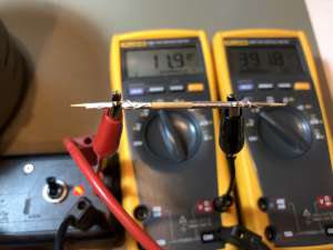
Measuring the resistance of a toothpick. (click to enlarge).
But it's an interesting material to test: let's find out how insulating it is. A toothpick has a comfortable shape and is made out of wood. I first took a dry new toothpick form a brand new box and hooked on my test setup and measured more than 300 GΩ: not the best insulator in the world but still respectable... but wait, let's make another test: let's disconnect the toothpick, hold it in the hand for 30 seconds and measure it again: this time its resistance dropped to 112 GΩ... hum, not as good as before. And there is also a surprising phenomenon: if you breathe or blow on the toothpick while doing the measurements, its resistance drops, significantly. This is probably due to the moisture present in the breathed air that is absorbed by the toothpick. I could observe values of 2 GΩ or less that quickly recover after you stop doing it. This is 100 times more conductive! Maybe you can make a hygrometer with it, but wood sucks as an insulator. For the final test, I dipped the (disconnected) toothpick in tap water, dried it with a cloth, waited 10 minutes to make sure it didn't look wet anymore and measured it again: 1.45 MΩ, about 200'000 times more conductive. This is definitely not an insulator anymore: not using wood as electrical insulator is a wise choice.
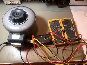
Measuring the insulation resistance of a small piece of insulated wire. (click to enlarge).
Let's now measure some "real" insulators: I took five small wire cutouts from a new three-phase cable. The insulation is stamped "PVC" on them. First, I removed the copper inside and tried to measure just the insulating material, but its resistance was too high and the DMM showed just 0.0 mV. It surely has some resistance but it's out of reach of this simple method. So I had to measure the insulation with the copper wire in it: the path of the current in the insulation is shorter and goes from the outside of the wire to the inside, moves a few centimeter aside and goes back to the outside again as illustrated in the picture below. I also measured the resistance from the outside to the inside of the wire insulation, finding about half the value. The aluminum foils wrapping the wires are about 1 cm long and 1 cm apart.
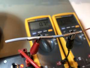
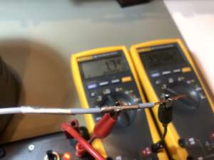
Picture of the measurement of the insulation from the outside to the
inside and back to the outside of a PVC insulated wire (left image) and from
the outside to the inside of the same wire (right image).
(click to enlarge).
All the wires measured in the 6 TΩ range except the black one which was only about 2 TΩ. It looks like this is normal, because the black pigment used to color the plastic material if often based on carbon particles that are slightly conductive. I have no mean to verify this hypothesis, but for sure my measurements show that the black insulation is more conductive than the other colors. This is usually not a problem, but it's maybe something to consider if you design an electrometer...
I also had a PVC insulated wire laying around that I used as an antenna in my garden for about a year before I replaced it with a bare copper wire. I measured its insulation resistance and find a surprisingly low value: around 500 GΩ. This is 10 times less what I just measured on brand new wires. I think the low resistance is due to damages caused by the weather (most probably by the UV radiation). Unfortunately, I don't have a piece of the same wire that was not exposed to the elements to compare to, so I cannot be sure. Still, it's an interesting measurement.
Finally, I tried to measure some other insulators: a piece of FR-4 PCB board (about the same dimensions of a toothpick), a glass microscope slide and a piece of PTFE (Teflon) tubing. The FR-4 checked out at around 4 TΩ, but I'm not sure this was really its resistance or simply some dirt on the surface. I wasn't able to clean it any better. By the way, it's good practice is to always thoroughly clean all the surfaces: dirt, dust, fingerprints, moisture and other contaminants may significant affect high resistance measurements. The glass and the PTFE were too high to be measured.
The following table summarizes my measurements. It's not an exhaustive list or a source of reliable data: it's just a collection of random measurements to illustrate what can (or can't) be measured with this method. I know they lack scientific rigor but they give an idea.
| Sample | Test voltage U0 | Measured voltage UM | DMM impedance RM | Resistor under test RX |
| Nothing - open circuit | 395.3 V | 0.0 mV ±0.20 mV | 10.00 MΩ | > 20 TΩ |
| 10MΩ resistor | 394.1 V | 194.3 V ±0.37 V | 10.02 MΩ | 10.30 MΩ ±0.04 MΩ |
| String of 5x 10MΩ resistors | 390.6 V | 64.58 V ±0.078 V | 10.02 MΩ | 50.58 MΩ ±0.07 MΩ |
| Toothpick dry out of the box | 391.8 V | 11.9 mV ±0.20 mV | 10.00 MΩ | 329.2 GΩ ±5.7 GΩ |
| Toothpick after holding in the fingers for 30 seconds | 391.5 V | 34.8 mV ±0.23 mV | 10.00 MΩ | 112.6 GΩ ±0.8 GΩ |
| Toothpick while breathing on it | 391.1 V | 1.620 V ±1.7 mV | 11.12 MΩ | 2.673 GΩ ±0.003 GΩ |
| Toothpick dipped in water and dried for 10 minutes | 392.3 V | 342.6 V ±0.5 V | 10.02 MΩ | 1.454 MΩ ±0.017 MΩ |
| PCV insulated black wire | 390.4 V | 1.8 mV ±0.20 mV | 10.00 MΩ | 2.169 TΩ [1.952...2.440] TΩ |
| PCV insulated yellow/green wire | 390.3 V | 0.6 mV ±0.20 mV | 10.00 MΩ | 6.505 TΩ [4.879...9.757] TΩ |
| PCV insulated blue wire | 390.5 V | 0.6 mV ±0.20 mV | 10.00 MΩ | 6.508 TΩ [4.881...9.762] TΩ |
| PCV insulated brown wire | 390.4 V | 0.6 mV ±0.20 mV | 10.00 MΩ | 6.507 TΩ [4.880...9.760] TΩ |
| PCV insulated gray wire | 390.4 V | 0.7 mV ±0.20 mV | 10.00 MΩ | 5.577 TΩ [4.338...7.808] TΩ |
| PCV insulated grey wire external to internal | 390.6 V | 1.7 mV ±0.20 mV | 10.00 MΩ | 2.298 TΩ [2.056...2.604] TΩ |
| PCV insulated blue wire after one year outside | 394.4 V | 7.1 mV ±0.20 mV | 10.00 MΩ | 555 GΩ ±17 GΩ |
| Piece of FR-4 board, about the size of a toothpick | 395.1 V | 1.0 mV ±0.20 mV | 10.00 MΩ | 3.95 TΩ [3.3...4.9] TΩ |
| Microscope glass slide | 393.8 V | 0.0 mV ±0.20 mV | 10.00 MΩ | > 20 TΩ |
| Teflon tubing | 394.2 V | 0.0 mV ±0.20 mV | 10.00 MΩ | > 20 TΩ |
To increase the contact surface, I wrapped the insulator in two small pieces of aluminum foil about 1 cm apart. This also prevents the alligator clips from biting into the insulation. It turns out to be quite difficult to wrap tiny foils in a consistent manner to make sure the surface and the distance between the electrodes are always the same. For what I was doing I didn't bother too much, but definitely something one should watch out for really accurate measurements.
My test voltage source just rectifies the mains voltage. Because the mains voltage is not regulated it changes all the time. Not by much, but a little bit. Therefore the rectified voltage also changes a bit and to avoid introducing additional errors, I monitor it with a second DMM so that I read both U0 and UM at the same time. If you use a battery (or a regulated power supply) you don't need to bother: just measuring U0 once is enough.
There is a little "bonus" with this method: you can also measure diode leakage current. This current is usually very low and tricky to measure. With this method you'll be able to measure easily down to 1 nA, maybe even below. This is enough for most common diodes, but I admit that those special diodes with leakages down in the pA range are out of reach of a simple DMM. Still, it's worth trying. The circuit diagram of the setup is almost the same, only the component under test is different:
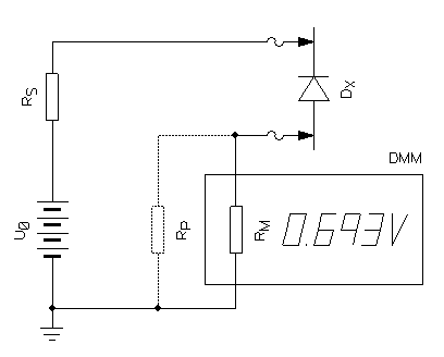
Circuit diagram of the diode leakage measurement setup.
Let's first spend a few words on diode leakage current: all diodes are supposed to let current through when directly polarized and completely block current when polarized in the other way (reverse polarized). So far so good, that's what diodes do. But real diodes don't really block current completely when reverse polarized; there is always a tiny current that finds its way through the blocked diode that is called reverse leakage current or simply leakage current. Not all diodes are created equal: some are specifically designed to keep leakage very low. But very often leakage is not an issue for the most common applications, so little is done by the manufacturers to control it, optimizing other characteristics of the diode instead.
Leakage current strongly increases with temperature, mildly increases with voltage and also depends on the very diode you are testing: they are all different, even if they are all of the same model from the same batch of the same manufacturer. Holding a diode in your hands will heat it up just a bit but is enough to change its leakage current by 30 % or more and you'll have to wait several minutes until is stabilizes again.
No diode can hold reverse current if the voltage is higher than its reverse breakdown voltage: the test voltage U0 must be selected wisely. Normally you're interested in the reverse voltage the diode will experience in your circuit, and that is the test voltage you should use. I arbitrarily used 30 V for most of the following measurements, because I just wanted to present here a bunch of different diodes. But for the OA90 germanium diode I choose 20 V, because its reverse voltage is exactly 30 V and I wanted to have some margin. If the diode breaks down nothing bad will happen because the impedance of the DMM is very high, limiting the current to a very safe value, but you won't be measuring leakage current anymore.
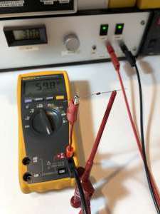
Measuring the leakage current of a 1N4148 diode. (click to enlarge).
In practice, start by selecting a suitable source voltage (test voltage) as explained and measure the leakage current using the internal impedance of the DMM as a high value shunt. It's almost the same thing that we did before to measure insulators: just replace the insulator with your diode. Make sure that you connect the diode in reverse polarity. Once you have the measured voltage UM, simply use Ohm's law to calculate the current (Ileak = UM/RM). I didn't provide a calculator for this; I think this formula is simple enough. If the voltage you're using is low (below 50 V) you can omit the safety resistor RS and use a current limited power supply instead.
These are a few diodes I tested, just out of my junk-box:
| Diode model | Junction type | Test voltage U0 | DMM Impedance RM | Measured voltage UM | Leakage current |
| 1N4148 | Silicon PN | 30 V | 10.00 MΩ | 59.8 mV | 5.98 nA |
| 1N4007 | Silicon PN | 30 V | 10.00 MΩ | 82.1 mV | 8.21 nA |
| BY550-600 | Silicon PN | 30 V | 10.00 MΩ | 75.2 mV | 7.52 nA |
| BAT43 | Schottky | 30 V | 11.12 MΩ | 2.456 V | 220.9 nA |
| MUR120 | Schottky | 30 V | 10.00 MΩ | 4.9 mV | 490 pA |
| 1N5822 | Schottky | 30 V | * 922.5 kΩ | 4.339 V | 4.703 μA |
| OA90 | Germanium point contact | 20 V | * 922.5 kΩ | 4.384 V | 4.752 μA |
| AA117 | Germanium point contact | 30 V | * 922.5 kΩ | 2.835 V | 3.073 μA |
| 2N2222 | Bipolar transistor C-E junction | 30 V | 10.00 MΩ | < 0.1 mV | < 10 pA |
| BC547 | Bipolar transistor C-E junction | 30 V | 10.00 MΩ | < 0.1 mV | < 10 pA |
| *:A 1.006 MΩ resistor has been connected in parallel with the DMM to lower its impedance. | |||||
Some diodes were surprisingly leaky; so much that almost the full supply voltage was appearing on the DMM, making me think the diodes were shorted or mounted backwards. These are the ones marked with a "*". I checked them with the diode test function of the DMM and they were "good" and were indeed mounted correctly, they are just very very leaky. So, I connected a 1 MΩ resistor in parallel with the DMM to lower its impedance and still measure their leakage current that turned out to be in the several microampere range. I knew germanium and some Schottky diodes are leaky, but didn't expect that much. Anyway, if you're interested in diode leakage, it's probably because you want a low leakage one... I can't think of any application where leakage is desirable, by the way. Very often it's acceptable, but not desirable. So, you'll probably don't need to go through the trouble of connecting an extra resistor... you already know that that particular diode is leaking like a sieve: just use a different one.
As a general rule, Schottky diodes have larger leakage currents, but not all of them: some are specifically designed for low leakage and are very good. Often high current diodes also have large leakages and high voltage diodes have lower leakages when used at low voltages.
By the way, the fact that a diode is leaking doesn't mean it's bad: it will probably work fine for the majority of common applications. It will be an excellent rectifier in your power supply, a good reverse polarity protection for your favorite battery operated amplifier, a trusty clamp for that relay inductor always willing to shoot high voltages all over the place,... applications requiring low leakage diodes are rare and often involve precision and high impedances. You may need them around an integrator, a sample-and-hold, the input of an ADC or anywhere a tiny current is significant.
Finally, here is a small "bonus trick": the base-collector junction of a normal bipolar transistor is usually a very low leakage diode. So, if you don't have a low leakage diode when you need one, try connecting the collector and the base of a transistor with suitable voltage and current (and leave the emitter open): it can save your day (and save you from losing three weeks waiting for that special expensive diode coming from across the Atlantic). Not as good as a true low leakage diode, but definitely a good trick to know.
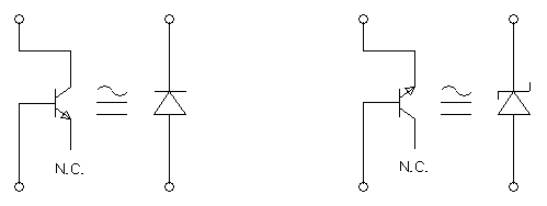
Diode equivalents of a bipolar transistor.
By the way, for the sake of completeness, the base-emitter junction of a bipolar transistor behaves like a Zener diode with a reverse voltage usually around 6 V.
A trick for extending the resistance measuring range of a common digital multimeter has been presented. It's really a simple trick, almost trivial, no rocket science here. But if you thought your DMM could only measure 50 MΩ, you should think again: you can actually measure 500'000 MΩ, maybe even more. Yes, that's four orders of magnitude larger. It can be summarized in just one sentence: "switch your DMM to voltage to measure current with an external supply". I'm sure it's something that can be handy one day, so I decided to share it.
| Home | Electronics | Page hits: 042128 | Created: 12.2018 | Last update: 12.2018 |