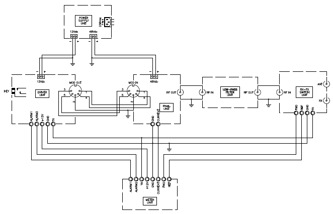
Block diagram of the transmitter (click to enlarge). – A PDF version is also available: blockdiagram.pdf (20,307 bytes).
I don't know why, but I have always been fascinated by long waves: maybe because of their strange propagation mode which changes slightly between day and night, but not too much; maybe because of the strange signals one can find in this band, something in-between noise and cryptography.
I spent a lot of time in listening to any kind of long-wave signal since I was a kid, but for sure, to operate in this band is not an easy task, since one cannot just buy a ready transmitter: none of the regular radio-amateur equipment manufacturer seems to be interested in producing one.
The plan to build my own transmitter is definitely not new and I was thinking of it since many years, but it was jus an idea lost between many others.
On December 31st, 2010, for economical reasons, the Swiss medium-waves transmitter in Sottens was shut down and the local radio club negotiated with the authorities the possibility to borrow the two antennas for one month to see how they work on amateur bands.
So, in February 2011 I met HB9ASB who already had his own long-wave transmitter and wanted to use the spare mast for the 137 kHz band. What a wonderful idea: a 125 m high antenna tower and a long-wave transmitter! This was the spark that ignited the long-waves passion again.
The first idea was to modify an audio amplifier in order to increase its bandwidth from 20 kHz to 150 kHz or more, but since I couldn't find a suitable amplifier and because it implied using a lot of transformers to couple all the channels together, I decided to build one from scratch.
At that time, some countries already allowed amateur traffic in the 500 kHz band and rumors says that this band may also be allowed to Swiss amateurs in a near future (at the time of writing, unfortunately, this is not yet the case). I wanted therefore that the same transmitter could cover both bands (137 and 500 kHz), just in case.
At 137 kHz, the efficiency of the antenna is so low that QRP is almost impossible. I needed a powerful transmitter, at least several hundred Watts. I therefore designed a 1 kW transmitter, strongly inspired from the one of HB9ASB. Finally I ended up with only 500 W because I couldn't find a suitable power supply transformer, but 500 W are fine for the moment to have some long-wave fun. When connected to an industrial 48 V power supply I borrowed from a friend, the transmitter was able to deliver 1200 W into a 50 Ω dummy load.
In the 137 kHz band, only CW and digital modes are allowed, therefore, to keep the circuit as simple as possible, a CW only transmitter has been designed. In the future, by modifying the DDS circuit, other digital modes like DFCW (Dual Frequency CW) should be possible.
The design is modular and each module is contained in a separate metal box: this allows testing and optimizing each module separately and brings down the complexity of the whole project. Using a lot of metal shielding also helps to prevent RFI and "strange" behaviors of the modules. The final result is not as nice like having one single box with everything inside, but it's much easier to modify or fix.
The transmitter is composed by the following units:
A block diagram of all the different units and how they are connected together is presented below:

Block diagram of the transmitter (click to enlarge). –
A PDF version is also available: blockdiagram.pdf (20,307 bytes).
A dual-band long and medium-waves kilowatt CW transmitter has been described. I hope these pages will help some other amateurs in building their own. This circuit is fully functional but still deserves some improvement: please consider it as a suggestion or as a starting point for a better transmitter. The major improvements that should be considered are a different and more energy efficient final configuration, a driver unit capable of different digital modes and a more efficient and compact power supply.
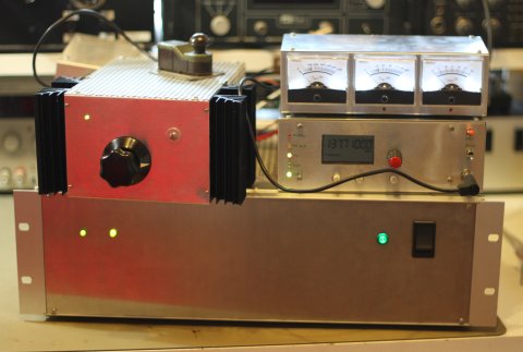
An global view of the assembled transmitter is visible in the following picture:

Complete LW transmitter (click to enlarge).
| Home | Electronics | Page hits: 029146 | Created: 05.2012 | Last update: 05.2012 |